Announcement

Collapse
No announcement yet.

GAI 3003 capper/crowwner semi-annual R&R--photo tutorial

Collapse
X
 
  • Filter
  • Time
  • Show
Clear All
new posts

  • GAI 3003 capper/crowwner semi-annual R&R--photo tutorial

    Well, it was time for my semi-annual capper maintenance, so I thought I'd get out the old Nikon and document it for you all. This is very photo-heavy, and for some reason, IMG code is turned off for me at this board, so you'll have to click on the links. All the links lead to one of my Flickr accounts, so they are safe.

    The assembly I'll be working on is the part of the crowner that goes up and down and actually puts the crowns on. The diagram is on pg. 76 of the GAI 3003 Bier manual. Please, ignore the "Adjusting the crown head closure position" instructions on this page--they are wrong! I'll explain the proper procedure when I put the critter back together.

    First, tools needed:


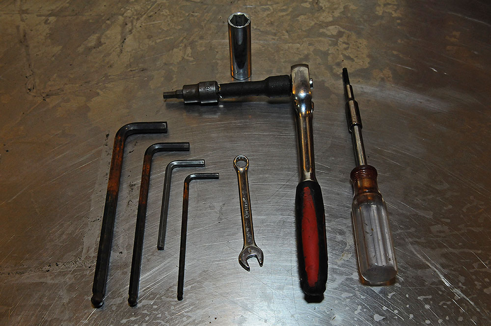
    A full set of metric Allen wrenches--we'll be using the 2.5, 4, 5, 6, and 8mm. A 3/8" drive X 6mm Allen ratchet wrench will make thing easier, but you can get by with the regular Allen wrench. Ditto the 4mm Allen on a 1/4" drive handle.
    14mm deep socket X 3/8" drive.
    1 1/2" X 3/8" extension.
    3/8" ratchet drive.
    8mm combination end wrench.
    Not in photo:
    2 or 3 3/4" cube steel blocks--you can probably get away with wood or plastic blocks, but if they fail....
    6" X 7mm hard steel rod. A 6mm Allen wrench will work, but the 7mm is much better. I ground a piece of 3/8" drill rod down.

    OK, let's get wrenchin'!

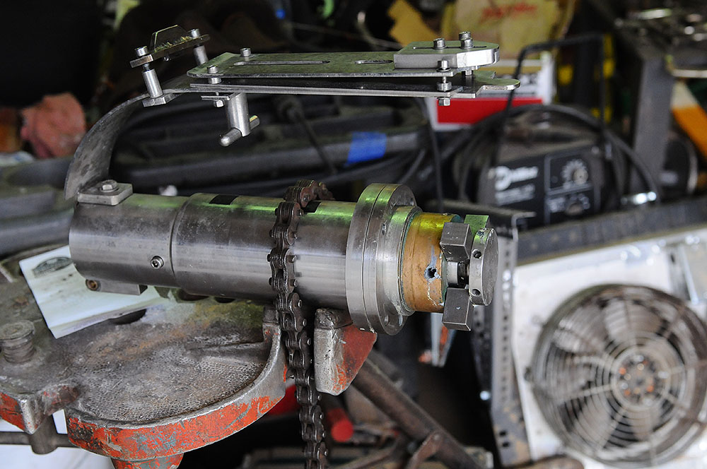
    With the capper at top dead center (highest point in its travel), loosen but do not open the gate that holds the lower caps channel closed. Using the 6mm Allen wrench, remove the bolt that retains the lower caps channel:


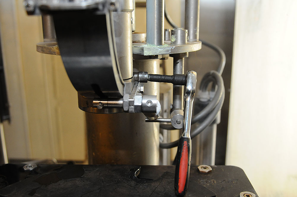
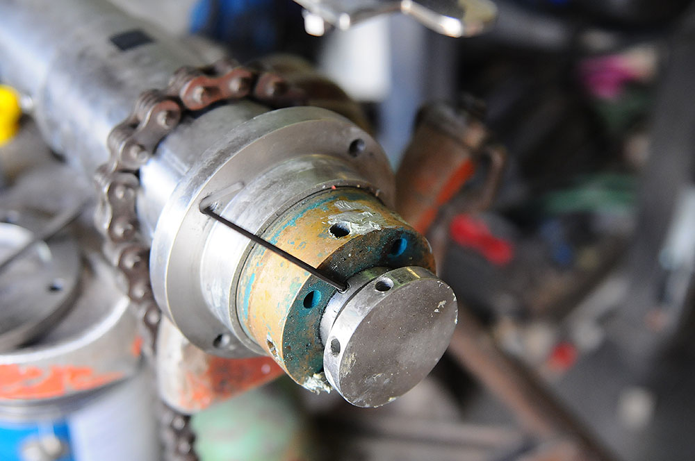
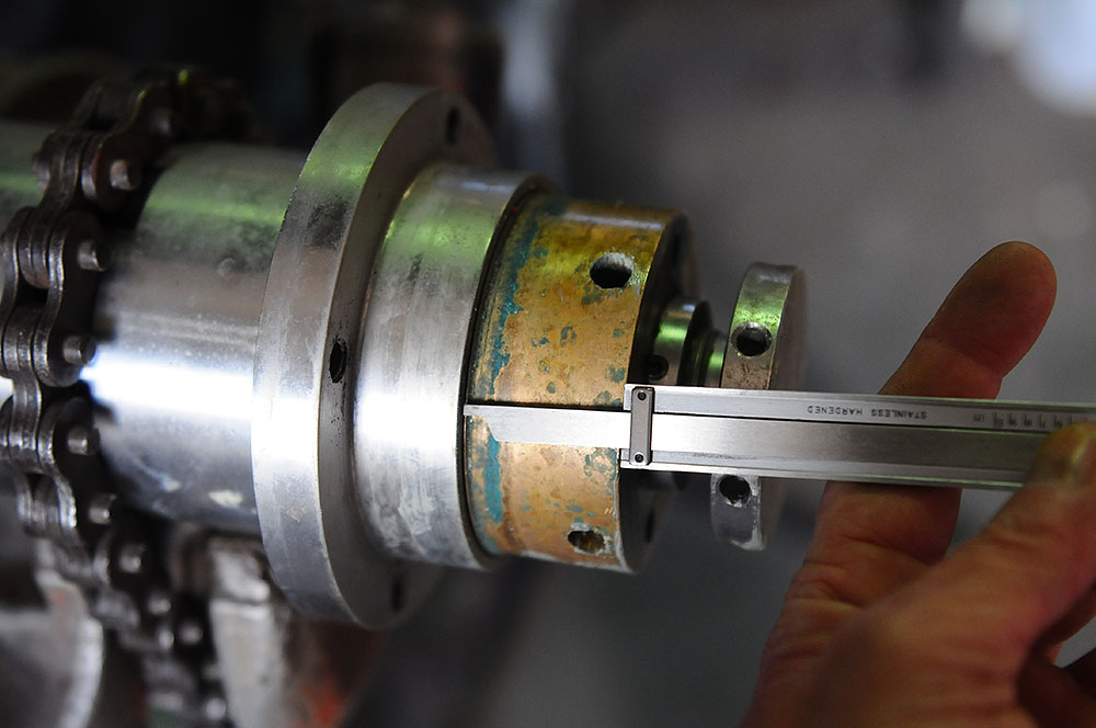
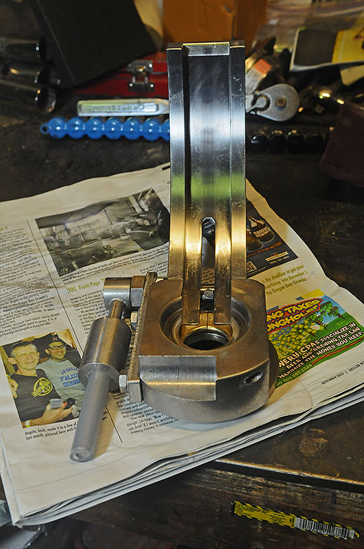
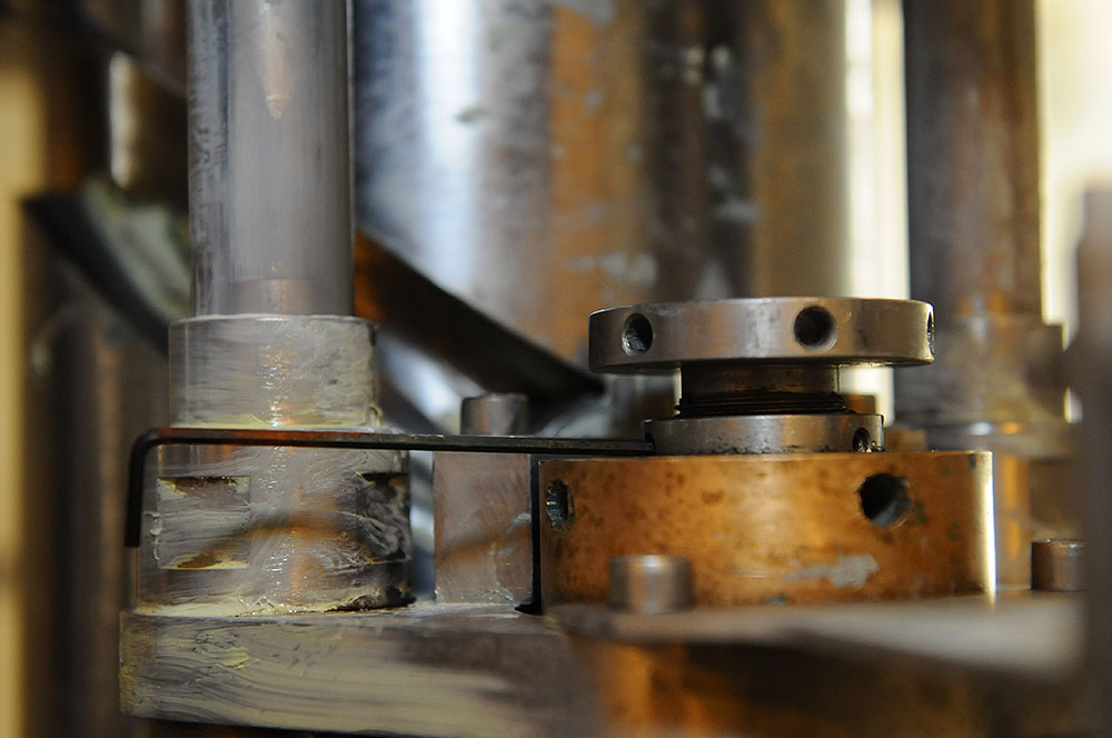
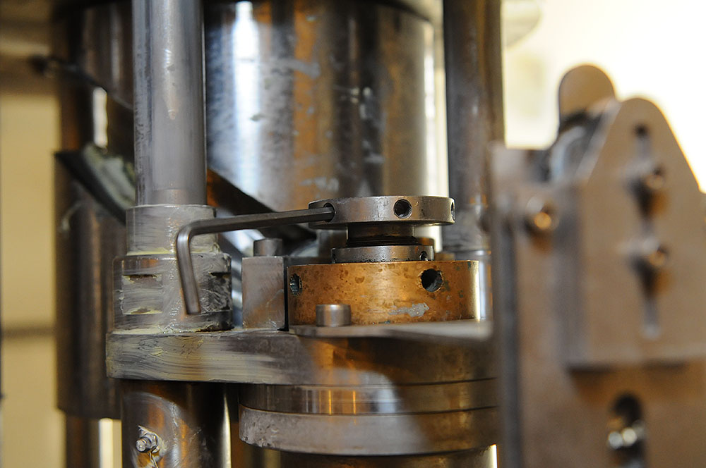
    With the 5mm Allen wrench, loosen the retaining screw for the crowner lower unit (on the right hand side of the crowner assembly):


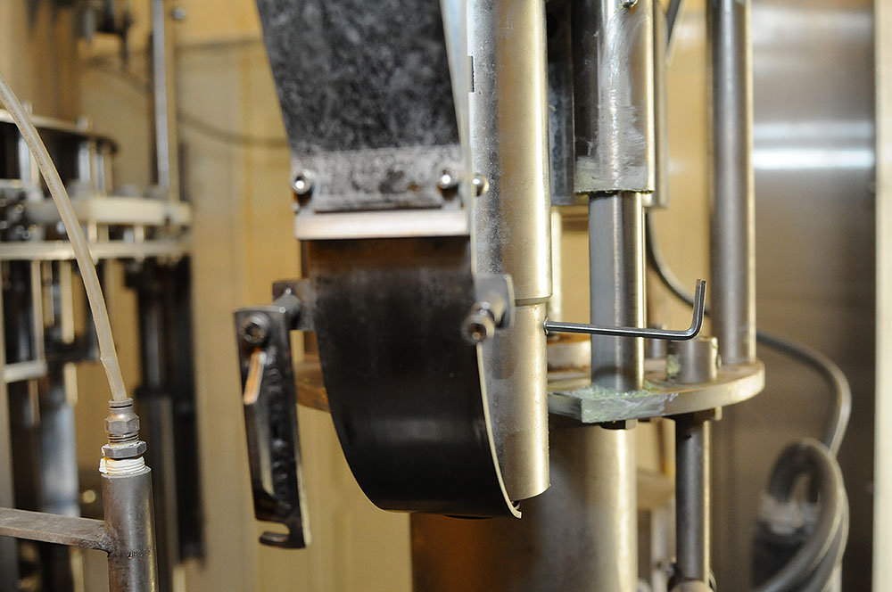
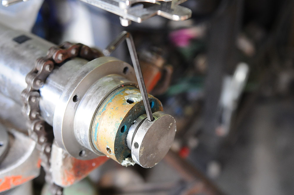
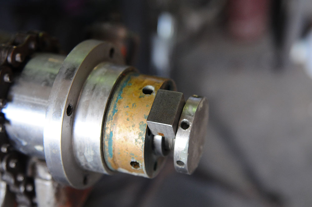
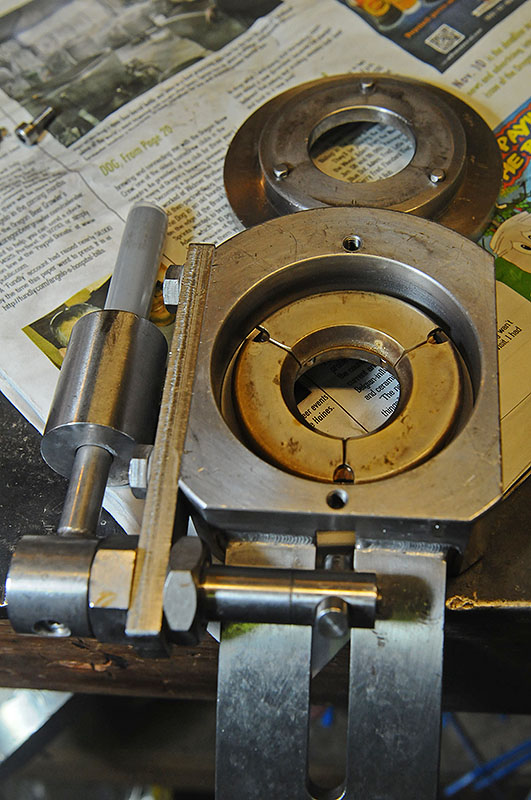
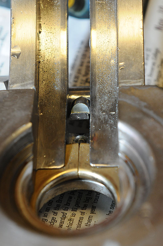
    The lower unit should slide right out, if not, you can use a 6mm Allen wrench in the bottom of the caps pusher (D in diagram on pg 76) to wiggle it loose:


    Advance the machine until the crowner assy is at bottom dead center--lowest point.

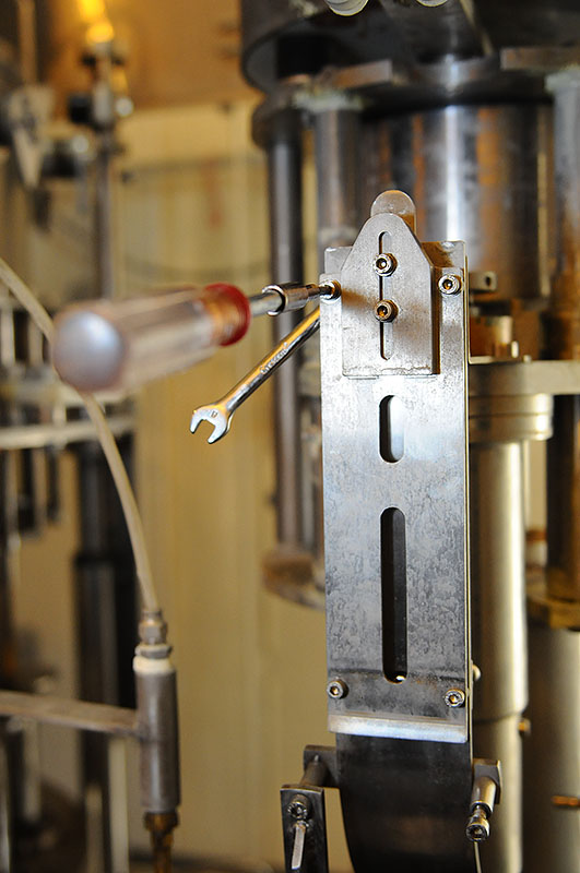
    With a 4mm Allen wrench and an 8mm combination wrench, loosen--don't remove--the screws that retain the lower caps sensor bracket:


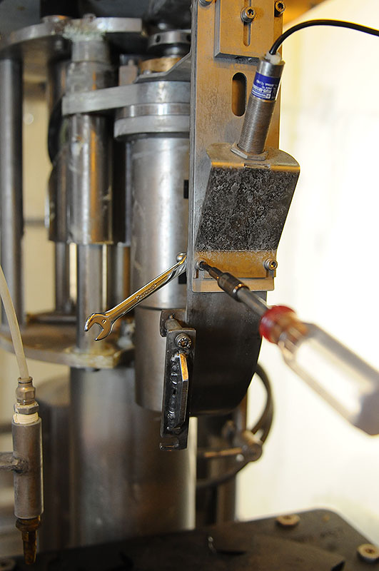
    and slide the sensor and bracket off. Let it dangle out of the way.

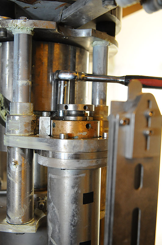
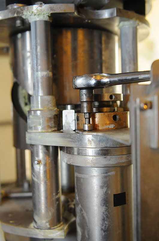
    With the 14mm deep socket, remove the greasy (it had better be) bolt with the Zerk fitting at the back of the top of the assembly:


    With the 6mm Allen wrench, slightly loosen all four bolts at the top of the crowner assy. Remove the front two bolts:


    This will free the top support for the caps back plate, but you still need to remove the nuts from the two screw at the top of the caps channel (4mm Allen wrench, 8mm combo) and remove the support piece:


    Be careful not to lose any washers or spacers, and screw the nuts back on--finger tight is fine.

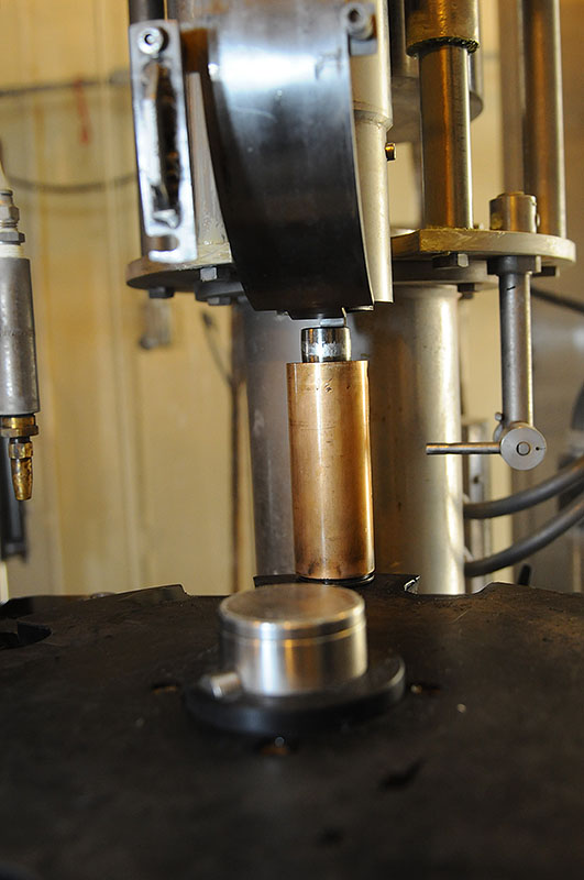
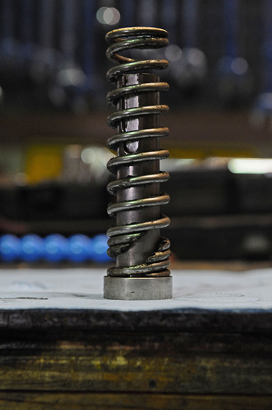
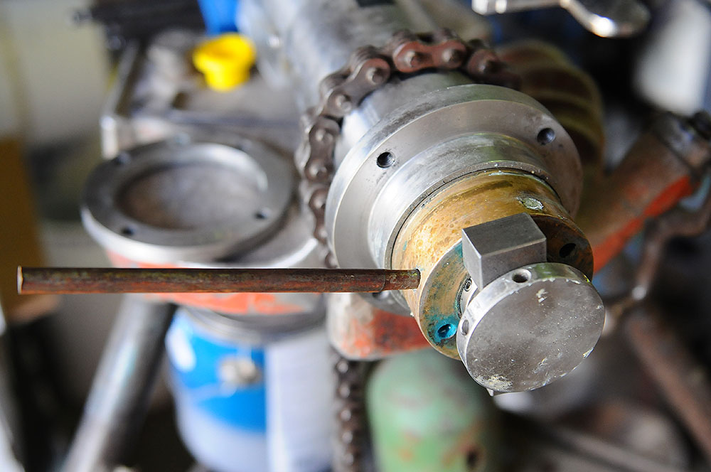
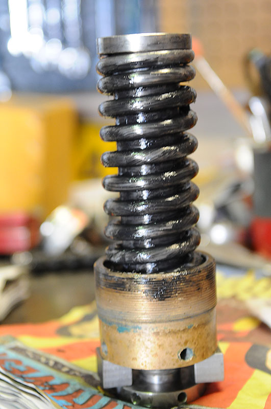
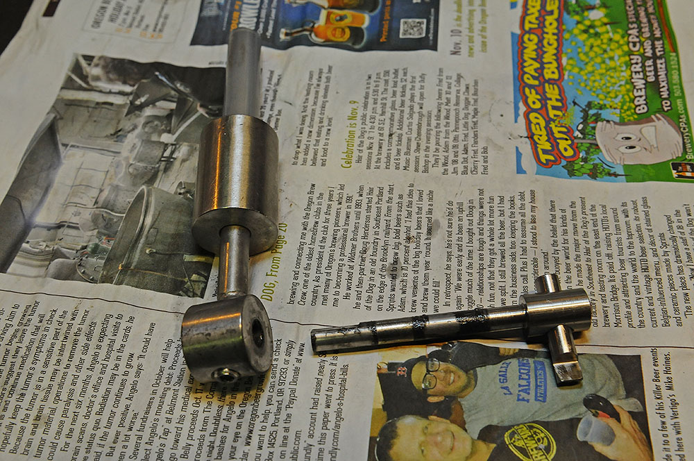
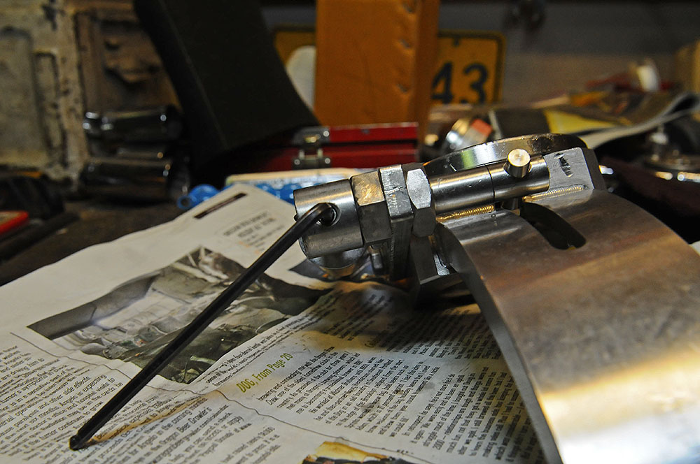
    Advance the machine until the crowner assy. is about 1/4-1/3 of the way up, and remove the remaining two bolts from the top (oops, forgot to get a picture). You might want a hand to catch and lower the rather heavy assy, but I manage it on my own. Pull the assy. down and out. Remove the drive cam follower assembly from the drive cam and inspect it for cracks/corrosion/wear. If the shaft looks like this:


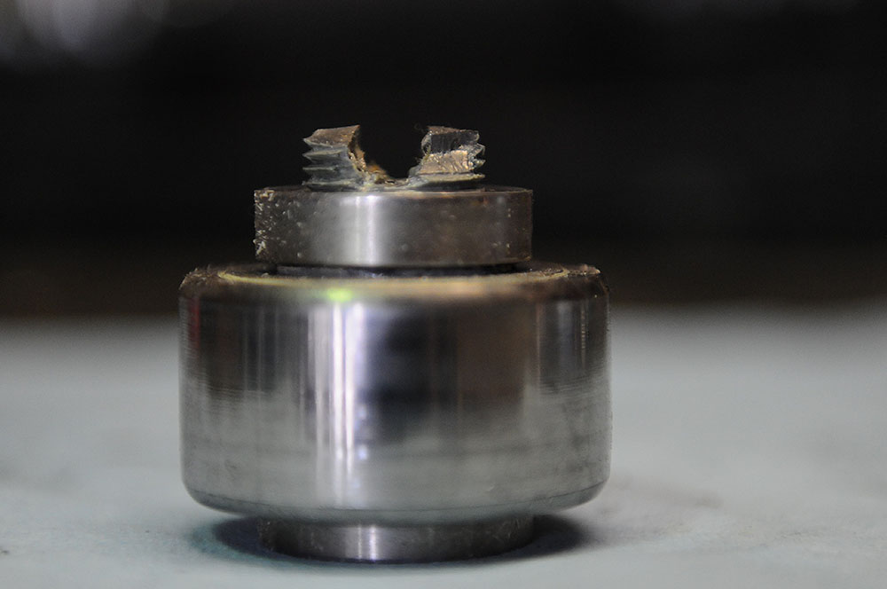
    You're going to be talking to Prospero--and you've put off this maintenance too long.

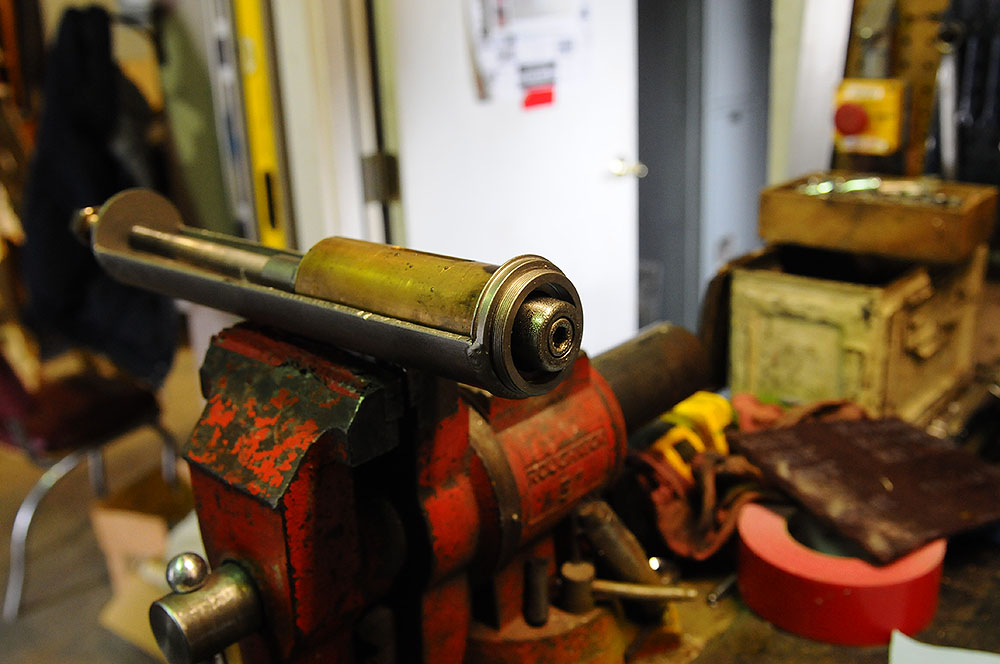
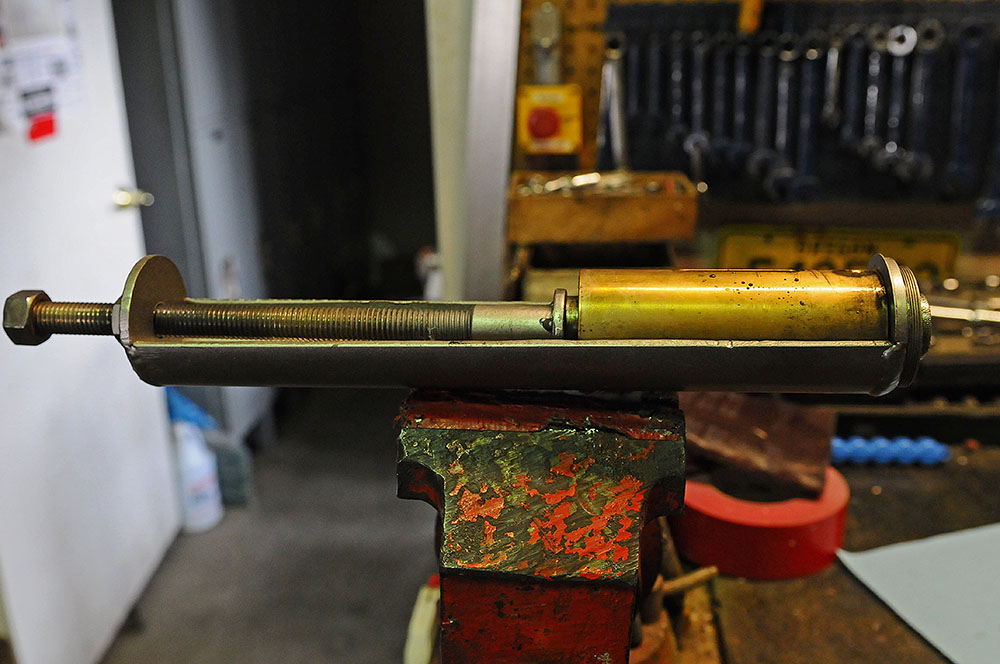
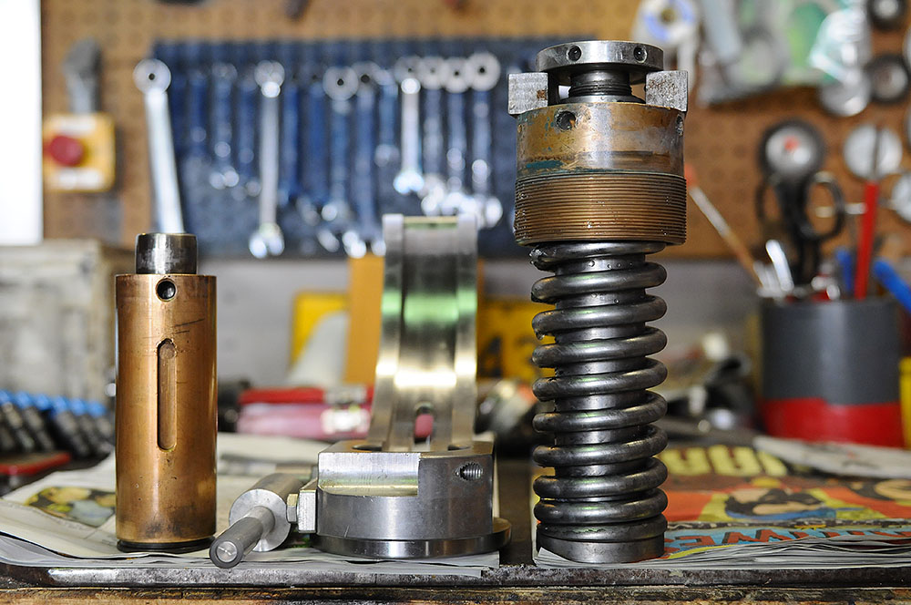
    Take the major parts back to the shop and open a beer!

    I'm going to take a break and try to finish this tutorial tomorrow.
    Last edited by TGTimm; 01-17-2014, 03:52 PM.
    Timm Turrentine

    Brewerywright,
    Terminal Gravity Brewing,
    Enterprise. Oregon.

  • #2
    Part 2

    So, back at it. We now have three pieces in the shop and ready to go.

    The lower caps channel and cap holder, hopefully, needs only be cleaned and lubricated with silicone spray. This should be done after every bottling run, as the foam from the fobbed beer will cement the moving parts together. Remove the two screws on the bottom of the unit and inspect the 3 brass parts that form the ring that holds the cap ready for capping. They should be uniform in shape and wear. Be sure that the o-ring that keeps them together is in good shape. Sorry, I have no pics for this part--maybe later.

    The lower capper unit--the part that has the cap closing cone, (I on dig. pg. 76), the cap pusher (D, pg 76), the centering unit (G) and the cap pusher spring--also needs to be rinsed after every run. I usually just remove the keeper screw (more on this later) to allow air to escape and dip the unit in hot H2O several times to get the beer out. Every three or four runs, I tear it down and clean and lube the spring and center shaft.

    The spring in this unit is large and well pre-loaded, and potentially very dangerous. If you don't have the tools to do this job properly, take it to a machine shop, or get the tools and be sure you know how to use them! I initially used some wood-working clamps to relive the spring, but I finally built a spring compressor and the job is now much easier and much less scary then it used to be.

    Here's the unit:


    Using a bench vise and 8mm Allen wrench, loosen--but do not remove--the screw that retains the centering unit (G). If you have a spring compressor or clamps, tighten the compressor or clamp so it holds the cap pusher (D) in the body of the unit. Remove the 8mm Allen screw and the centering unit (G). Slowly let the pressure off the pre-loaded spring, and take the center shaft and spring out of the main body.

    Here's my DIY spring compressor and the lower unit:


    The throw of the spring compressor only needs to be about 8 inches, I built this one long so I can use it to tear down a spring-driven airgun of mine.

    Here are the guts of the lower unit:


    If your spring looks like this:


    it's time for a new one. It's a good idea to replace this spring every year or two. I replaced this one (the unbroken one) after about two years, and the new spring was a full inch longer than the old! This spring is one of the harder working parts of the entire capper, so it sees a lot of wear and tear.

    I wash all the parts in hot H2O, then lubricate the shaft with a good quality molybdenum grease. Yeah, this should be a food-grade grease, but the amount of wear on this part is heavy and I wouldn't trust the FG grease unless I re-lubed after every run. By keeping the grease light, I've yet to see any on a cap or bottle.

    Put the spring, shaft and body of the lower unit back into the spring compressor and carefully push them back together. Insert the screw into the centering unit (G) and tighten it until the inner shaft starts to turn. Looking into the retaining screw hole (at the top of the unit above the slot), get the slot of the inner shaft aligned with the screw hole and insert the retaining screw. You can now safely remove the lower unit from the spring compressor. Holding the lower unit bod tightly in a vise or clamp, tighten the center screw to about 30 ft/lbs. Remove the retaining screw--the one above the slot in this picture:


    and put it somewhere you won't lose it. The only use I have for this screw is to keep the inner shaft from rotating when I'm taking the unit apart or reassembling it. In use, it will tend to back out of the lower unit body, causing the entire lower unit to jam within the body of the capper. This will cause no end of headaches, so just leave the danged thing out. I've been running without this screw for a couple of months, and the capper has never worked better.

    Now for the main body of the capper. This houses the compensating spring (C, pg. 76), the limiting pin (A), and the compensating spring pressure tube (F). Her's the main body ready to be disassembled:


    I don't have a spring compressor large enough to completely tear this unit down (yet), so this sill be a simple clean and lube.

    With a 2.5 mm Allen wrench, loosen the three grub screws (B) that retain the limiting pin:


    and, using a 6mm Allen wrench, back the pin out


    until you can fit the 3/4" steel blocks between the cap of the limiting pin (A) and the compensating spring pressure tube (F). Screw the pin down until it's tight against the blocks:


    DON'T SKIP THIS STEP! There's a very large, highly loaded spring in this unit, and it will not get loose, but will make it near impossible to get the unit back together if it isn't retained! Ask me how I know....

    Now use a fine-scale ruler or caliper to measure the amount of the compensating spring pressure tube that is exposed above the main body. This distance determines the amount of pressure that the cap is seated with, and if it's too great, bottles will burst. Too light, and the cap will leak. Hopefully, it's properly adjusted already, so by measuring it, you can return to this setting when we put the critter back together.


    Now, unscrew the compensating spring pressure tube from the main body of the capper. This is where the 7mm rod comes in handy. In a pinch, a 6mm Allen wrench or 1/4" drill bit will suffice:


    Now we have the guts out of the main body. Here it is, with the lower unit and lower caps channel/caps holder:


    I've had the spring and shaft steam-cleaned, but a good wash-down with very hot H2O and de-greaser would work as well.

    Using a good quality molybdenum grease, re-grease the spring and shaft--this is plenty of grease; don't over-do it:


    Make very sure that you don't get any grease or oil whatsoever in the cavity at the bottom of this assembly! The centering unit of the lower unit moves up and down in this area with enough speed and force to cause any organic lubricant in the cavity to Diesel! BOOM! Once again, ask me how I know....

    Alright. It's time for a break. I'll get every thing back together and adjusted in the next installment.
    Timm Turrentine

    Brewerywright,
    Terminal Gravity Brewing,
    Enterprise. Oregon.

    Comment


    • #3
      Re-assembly

      Well, hope you all had a nice weekend--I know I did.

      At this point, the lower unit is greased and reassembled, the upper unit is greased and still torn down. Let's go on from there.

      Take the main body of the capper out of your vise or tri-stand, and either wash it out thoroughly with very hot H2O or have it steam-cleaned. Since the spring is already greased, there's no reason to add any more. Clamp the main body down again, very lightly grease the threads of the compensating spring pressure tube (E on pg 76), and very carefully align the threads and start screwing the spring unit back into the main body. Since the male threads are brass and the female SS, it's easy to get this started cross-threading, so take it easy and make sure everything is lined up properly.

      With your 7mm rod or whatever you used, tighten the spring unit into the main body until the amount exposed matches your earlier measurement:


      Loosen the limiting pin (A) until you can slide the steel blocks out. Tighten the pin a couple of turns--don't worry too much about how much as we'll be adjusting this later. Leave the three grub screws (B) loose.

      Optional step: the large spacer that sits atop the main body of the capper is not secured nor indexed, and can be a bit of a fiddle to get lined up when re-installing the unit--especially single-handed. Clamp the main unit upright and carefully and completely clean and degrease the top of it and the entire spacer. Use two of the retaining screws to index the spacer (make sure the fifth, smaller, hole is aligned), and run a bead of Loc-tite #609 general purpose retaining compound (green) around the top of the spacer where the main unit passes through it. The Loc-tite will draw into the gap and hold the two pieces together nicely. Let sit for about ten minutes.


      Now the main unit is ready to go back into the capper tower. This is just the reverse of the removal. Check that the holes in the drive cam follower shaft and retainer are lined up by passing the threaded tube with the Zerk fitting on top through the hole. If it doesn't go, give the shaft a half turn either way until it does. Insert the cam follower bearing into the slot in the drive cam. Lift the supporting ring up while inserting the main capper unit into it. Using two of the back (long) screws, start the threads and gently and evenly tighten them until the main unit is just tight to the support ring. Insert the threaded tube through the cam follower retainer and screw it in finger-tight. This operation goes much easier with another set of hands, but can be single-handed.

      Remove the nuts from the two screws at the top of of the lower caps channel (don't lose those spacers!) and install the L-bracket, short leg up, loosely onto the caps channel. Insert the last two big mounting screws through the long leg of the L-bracket and thread them just a bit more than finger-tight into the main unit.


      Give all the retaining screws of the main unit a quick tighten--not too tight. Tighten the two little screws at the top of the channel and the L-bracket at this point.


      Advance the machine until the capper unit is at top dead center and check to see if the backs of the two parts of the caps channel are lined up. If not, loosen the two big front retaining screws and align the channels. Holding them aligned, tighten the two big retaining screws into the main unit to about 30 ft.lb. Advance the machine until the unit is at bottom dead center and tighten the last two big bolts. With the 14mm deep-socket, tighten the threaded tube--gently--to no more than ~10 ft. lb. A little bit of blue Loc-tite on those retaining screws wouldn't hurt, and might be good insurance.


      Grease the drive cam follower bearing through the Zerk on this tube, using FG grease, until a bit of old grease squeezes out of the bearing. This should be lubed after every bottling run.

      Lightly clean the lens of the lower caps sensor and slide its bracket over the two small screws at the bottom of the lower caps channel. Tighten the screws.


      Gotta go--I'll be back.
      Last edited by TGTimm; 01-21-2014, 02:04 PM.
      Timm Turrentine

      Brewerywright,
      Terminal Gravity Brewing,
      Enterprise. Oregon.

      Comment


      • #4
        Final assembly and adjustments

        Alright--I got the problem with the World Tandem labeler fixed... well, I got it to work, anyway. For now.

        We now have the main assy. of the capper nice and clean and lubed and back in place. Now it's time for the lower assemblies--and adjustments.

        First, the caps Closing Cone (I, pg 76). Remove the CC from the capper lower assy, and inspect the inside for damage. These things are made out of pretty hard steel, but they do wear out.


        The CC on the right is fairly new and in fair enough condition to be good for quite a while still. The one on the left shows pitting, irregularity (out of round), and severe wear. Caps were sticking in it and breaking bottles.

        Put the CC back in the lower assy and stand it up-side-down. Using a straightedge, make sure the caps pusher (D) and the CC are flush with each other--or at least within a few thousandths of an inch.


        If they aren't, add or remove some of the shims (H) that should have come with the machine, located beneath the caps pusher (D). If you've lost or never found the shims, cut some from a beer can--PBR cans are reliably 5 thousandths of an inch. Use lots of blue Loc-tite when you screw the caps pusher back in--this is not something you want to come loose during a run.

        With the CC back in place and adjusted, it's time to put the Lower Unit back into the main assy. Lightly spray the LU with some FG silicone--test the silicone spray for flammability, some use butane for a propellant. If the fresh spray will ignite, let it dry completely before proceeding. I think this is what Dieseled and blew the lower crowner apart on me a while back. Turn the LU so the slot on the outside faces your right, and gently slide it into the main body. It should slide smoothly and easily into the body. If it encounters any resistance, you have serious problems. Don't proceed until you've cured them. The usual prescription involves chanting, ranting, prayer, and/or sending Prospero some more money. With the 5mm Allen wrench, screw the LU retaining screw back into the main body. The screw should go in to about flush with the body:


        If not, you've missed the slot. Keep turning the LU until the screw goes in. Do not tighten this screw! When the screw bottoms out, back it off about 1/4-1/2 turn! The LU must float freely within the main body of the capper or really bad things happen--broken glass and broken parts--and more offerings of money to Prospero.

        Now for the lower caps channel assy.


        This assembly should be cleaned after every bottling run. We use an ultrasonic parts cleaner, but hand-washing is fine. The main point is to get the beer out of it so it doesn't get glued together--and to keep things clean and sanitary. Lightly lubricate the caps channel portion with FG silicone spray, then remove the bottom plate:


        Make sure all these parts are clean and in good condition. Lightly lubricate all the parts in here with FG silicone spray, then carefully reassemble it. Be sure the three segments of the cap holder (brass) move freely before tightening the two Allen screws. Be sure the counter-weight on the caps retractor arm is centered between the two bolts on the side of the assy. The retaining screw can come loose, allowing the weight to shift until it hangs up in those bolt heads. Another good place for some blue Loc-tite.

        Every few runs, take the caps retractor assy apart and make sure the shaft isn't badly worn. Clean the shaft, lube it with some good quality FG grease, and reassemble it.


        Be sure this screw


        is tight. Use a drop of blue Loc-tite to keep it that way.

        The caps retractor itself--the little finger that pulls the second cap back-


        -is a fiddly adjustment. I prefer to have it just high enough to catch the edge of the cap, but not high enough to lift the cap against the fixed part of the caps channel. It must be perpendicular to the caps channel. A 4mm Allen wrench will loosen the adjusting screw for this. Good luck.

        Install the lower channel assy. onto the main body. This is the reverse of removing it. No special tricks here, but a little blue Loc-tite on the threads of the retaining screw will help to keep if from loosening. Tighten the screw until the channel is a little bit tight when swinging it down.


        There--it's back where it belongs.

        The next adjustment is the finger that moves the caps retractor:


        This is about where and how I like it--YMMV. The spring-loaded finger should sit about level, the spring tension will be up to you to determine. I like a couple of turns past neutral. The finger should lift the retractor high enough to move the second cap--the next one to be applied--about 1/2 cap widths. Too high, and caps will get crushed or bent at the top of the caps channel--it only takes a little bit to foul things up.

        More tomorrow--I'm off for a beer--
        Last edited by TGTimm; 01-22-2014, 11:53 AM.
        Timm Turrentine

        Brewerywright,
        Terminal Gravity Brewing,
        Enterprise. Oregon.

        Comment


        • #5
          Adjusting the capper height and caps closure

          We're going to need a half-dozen or so empty bottles (one full bottle is also handy), and another tool to do this right--a go-no-go cap crimp gauge. Talk to your caps provider about this, we got one free from ours.

          Tighten the gate that holds the lower channel closed, open the caps keeper plunger, and get ready to start adjusting the caps closure.

          With the machine set to manual, place four or five empty, uncapped bottles on the capper infeed conveyor. Run the machine until one bottle is located directly below the capper and the capper is at top dead center--this is critical.

          Consult the GAI manual again--there's a table of heights settings on pg 48--these are the numbers we need. Again, ignore step #6 on pg 76, "Adjusting the crown head closure position". These instructions will simply drive you mad.

          From the table on pg 48, we find that the proper height for the crowner is 60mm from the rim of the bottle to the bottom of the capper asssy:


          If this setting isn't where it should be, loosen the two black handles low on the right-hand side of the big capper column and, going to the Settings panel of the touchscreen, raise or lower the crowner until the height is right. We only bottle one size, so we don't use the automatic heights adjustment. If you bottle more than one size, consult the manual for setting the various automatic setting for your bottle size. Good luck.

          Now, run four or five bottles through the capper, again on manual. Using the go-no-go caps crimp gauge, check the crimp of the caps--you'll need to consult with your caps and bottle suppliers for the proper crimp closure:


          That's a go, this is a no-go:


          Don't force the gauge over the cap--just let gravity do the work. The skirt diameter of the crimped cap is something you should consult with your caps and bottle suppliers about.

          If everything is to your spec (yeah, right), you're ready to bottle.

          If not, I'll be back after lunch to, hopefully, finish this long-winded tutorial.
          Last edited by TGTimm; 01-22-2014, 04:17 PM.
          Timm Turrentine

          Brewerywright,
          Terminal Gravity Brewing,
          Enterprise. Oregon.

          Comment


          • #6
            Adjusting the capper height and caps closure

            Oops- double-posted the last installment.
            Last edited by TGTimm; 01-22-2014, 04:20 PM.
            Timm Turrentine

            Brewerywright,
            Terminal Gravity Brewing,
            Enterprise. Oregon.

            Comment


            • #7
              Adjusting the caps closure

              Good lunch.

              So, the caps are not crimped properly, or bottles broke, or both.

              This is the area we're working with right now:


              The center pin (A on pg 76) is what determines how far into the closing cone (I) the cap and bottle head go before the compensating spring starts to do its thing, and therefore how tight the crimp is.

              Be sure the three set screws (B on pg 76) are loose. Insert a 6mm Allen wrench in one of the holes in the center pin (A on pg 76)


              If the caps are too loose, screw this pin in (CW). If too tight, unscrew it (CCW). If bottles are breaking, unscrew it several turns, other wise, it takes some pretty small adjustments--fractions of a turn--to get the cap crimp just right. Test, adjust, repeat until satisfied. Be sure to remember to tighten the set screws when you've got it where you want it!

              Now run a dozen or so test bottles through the capper at your normal rate of bottling, and check the crimps again. Should be the same, but it's worth checking. I test a few bottles every hour or so during a run, just to be sure.

              Re-check all your work, making sure everything that should be tight is, and everything that should move free is doing so.

              Bottle some beer!


              Re-cap on some points:

              Things to clean after every run:

              Lower unit:


              Rinse with hot water to remove beer. Rinse the cavity within which it sits. Spray the outside with FG silicone and let dry before reinstalling.

              Lower caps channel and caps holder:


              Clean thoroughly and spray all moving parts with FG silicone.

              After every three or four runs:

              Disassemble, clean, and lubricate the lower unit:


              and the caps retractor shaft:


              Semi-annually:

              Do the whole Monty:


              Thanks for sticking it out through this lengthy explanation. If a picture is worth a thousand words, how much are several thousand words and a couple dozen pictures worth?

              Hope this is of some help to someone, and that I haven't made too many mistakes--
              Last edited by TGTimm; 01-22-2014, 01:54 PM.
              Timm Turrentine

              Brewerywright,
              Terminal Gravity Brewing,
              Enterprise. Oregon.

              Comment


              • #8
                Was this of any use or interest to anyone?
                Timm Turrentine

                Brewerywright,
                Terminal Gravity Brewing,
                Enterprise. Oregon.

                Comment


                • #9
                  It certainly isn't a casual read but I think a 3003 is in my future so I have it bookmarked for sure. The first time I actually need it, I'll owe you a beer.
                  Nat West
                  _____________________
                  nat@reverendnatshardcider.com
                  503-567-2221

                  Comment


                  • #10
                    Thanks, Nat.

                    We're in the process of getting a new company website set up, and I'm trying to get a blog or something going there where I can post tutorials like this (maybe try to be a bit more concise). I'll post a link on the GAI thread here when and if this happens. I'd like to have a record of these things for whoever takes over from me... someday.
                    Timm Turrentine

                    Brewerywright,
                    Terminal Gravity Brewing,
                    Enterprise. Oregon.

                    Comment


                    • #11
                      Semi-annual reminder!

                      It's time again, folks.
                      Timm Turrentine

                      Brewerywright,
                      Terminal Gravity Brewing,
                      Enterprise. Oregon.

                      Comment


                      • #12
                        Your tutorials have been incredibly helpful! After 4 months I'm still trying to learn and understand this machine and frankly, a lot of it has been over my head. Have you had any experience with crowns not feeding into the machine at the rate they should? I've adjusted the vibration numerous times but we still cant get it right.. It causes low fills and slows the rate at which we run. I'm going to do maintenance on the capper tomorrow as not much has been done after a year but I feel like it's some type of issue with the vibration level.. any insight?

                        Comment


                        • #13
                          Hmmm....

                          The driver for the vibratory crown feed has changed a couple of times over the years. The original one on our 2006 machine was under-powered and very problematic. This unit had two potentiometers mounted on the face of the unit, and required opening the back of the control panel to access the pots. Correct adjustment was a PITA, and would change during the run, requiring near constant fiddling to keep the crowns feeding. Fortunately, that unit finally went belly-up, and we replaced it with a newer unit (for $2,600). The new one has only one potentiometer mounted on the unit, with a second pot mounted on the face of the main control panel, next to the touch screen. If this is the one you have, the settings are much simpler. The knob on the unit itself adjusts the frequency, which should be set to 50 Hz using the display on the unit. The knob on the front panel adjusts the amplitude of the vibration. I set this by sound and by watching the crowns as they feed--a convex mirror mounted over the crowns bin greatly simplifies this (and makes keeping the bin full much easier). What you want is the highest amplitude (most noise) that does not cause crowns to jump off the feed ramp before entering the covered portion that rejects up-side-down crowns.

                          That covered section is also very finicky and needs to be carefully adjusted. The main adjustments are the clearance of the cover of the channel over the crowns as they feed. Place a crown on the feed ramp, and using a feeler gauge, make sure the clearance is about 0.010" (at least, this is what works best for us, using 26mm crowns). The clearance at the exit end should be the same.

                          Next, the little gate that allows up-side-down crowns to drop through the ramp must be adjusted properly. This is mostly a matter of trial-and-error. I push the crowns through by hand and set that gate to where the right-side-up crowns just stay in the feed. This gate on our machine broke loose--there's a screw that attaches the crescent-shaped gate to the arm that holds it, which is tack-welded, and the weld had broken, allowing the gate to rotate on the arm. A tiny bit of mis-alignment stopped the crowns from feeding. I was able to line the broken weld back into place and re-weld it.

                          One more thing to pay attention to--the crowns bin and the feed channel around it MUST be kept dry. A very little bit of moisture here completely gums things up.

                          Our machine currently has no problem keeping up with the crowner at 3,000 bottles/hour. It can be done, but I beat my head against the wall for a couple of years before I finally got it right!

                          Now if I can just find the cause of the irritating flurries of bent crowns that suddenly appear after the crowner has been running flawlessly for days....
                          Timm Turrentine

                          Brewerywright,
                          Terminal Gravity Brewing,
                          Enterprise. Oregon.

                          Comment


                          • #14
                            Bump--it's that time again!
                            Timm Turrentine

                            Brewerywright,
                            Terminal Gravity Brewing,
                            Enterprise. Oregon.

                            Comment


                            • #15
                              Vibrator adjustment

                              Tim thanks for all the wonderful information. It has made my job much easier!

                              I am having a problem with the vibrator, it has a new control unit thanks to a almost fire that fried the other one. I have the inside dial set to 50.1 Hz and the outside dial is all the way up. The inside display reads 255 and the crowns will not keep up with us running at even 2300 bph. Any suggestions? The unit just does not shake the crowns like it should. I have been on the phone with Prospero but no real luck in getting it solved. One thing I did get was the clearance needs to be perfect between the motor and the magnet and I feel like I am very close there.

                              Cheers!

                              Jeremy Gilbert
                              Crown Valley Brewing and Distilling
                              Brew master

                              Comment

                              Working...
                              X